
Since I started working, I've had the opportunity to witness numerous 4-20 mA installations and loops, both active and passive. I've also collaborated with a wide range of professionals, from novices to seasoned experts. One topic that has always generated interest and debate is the maximum distance achievable when transmitting a signal in the 4-20 mA range.
To provide some context, we typically work with PLCs or DCSs. In some situations, we encounter instruments located at considerable distances, such as more than 500 meters, 800 meters, or even 1000 meters or more. This considerable distance raises the question: "José Carlos, is it possible for a 4-20 mA signal to reach that distance, or is it necessary to consider another transmission method to get the signal to the PLC or DCS?"«
In this article, my goal is to explore both the theoretical and practical aspects to help you answer this question. I also want to share my perspective and address the economic factors involved. While I won't delve into exhaustive theoretical calculations, I will provide an overview to help you understand the key factors to consider. For detailed calculations, you can find additional resources online or consult the links I'll provide.
Theory, always theory….
Theoretically, the main factor determining the theoretical distance a 4-20 mA signal can transmit, or the maximum cable length we can use, is ensuring adequate voltage levels throughout the circuit and optimal for powering our transmitter or instrument. We often worry about voltage drop in the cable, but this is a mistake. If we check the datasheets for cables used for 4-20 mA transmission, we're talking about an approximate loss or impedance of between 15 and 30 ohms per kilometer. While it's necessary to consult the datasheet for precise details, this is the general trend. In short, we're talking about a loss of 30 ohms per kilometer.
To better visualize this, let's do a simple calculation. Suppose you have a 24-volt DC (VDC) power source and you're transmitting 20mA over 1 kilometer of wiring (30 ohms in this example). Performing this simple calculation (0.02A * 30 ohms = ? V), it becomes clear that the voltage drop per kilometer of installed wiring will be minimal. In fact, you'll likely only start to notice a real or concerning impact after traveling several kilometers.
A second, and more important, aspect to consider is the resistance of the analog input (AI) or analog output (AO) card, as well as the resistance of the instrument itself. Here, it's crucial to focus on the analog card. This card might have a resistance of 250 ohms as a normal value, but it could even reach up to 500 ohms. Again, check the datasheet for greater accuracy, but this is an approximation. It's important to note that this inherent resistance of the cards is much greater than the resistance of the cable itself over a given distance, and therefore a greater voltage drop will occur (perform the same calculation as before).
To help you with this theoretical topic, I'll provide you with a calculator through this link: https://www.divize.com/techinfo/loop-voltage-calculator.html. With this tool, you can enter the relevant data and clearly see the voltage that will be reaching your equipment or instrument at the end of the entire circuit. As usual, you should enter the data using a pessimistic or worst-case scenario approach.
For example, regarding current, while the maximum current you'll transmit is 20 mA, you could consider 24 or 25 mA. As for the wire gauge, opt for at least 18 AWG or smaller. For the power supply, instead of using 24V, you can use 22V, since we know power supplies aren't perfect. Regarding the resistance for the receiver (i.e., the board or module of your PLC or DCS), you can use 500 ohms, which would be the worst-case scenario. With this information, you'll obtain the voltage reaching the Loop Tester (see graph below); that is, you'll see the voltage that will power your instrument.
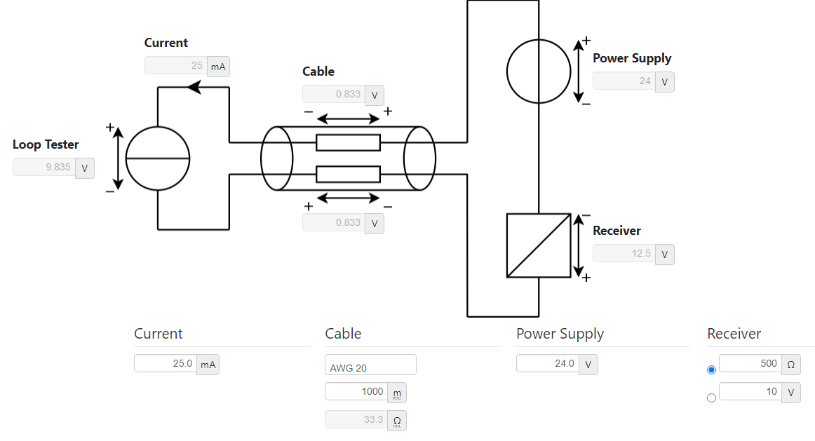
The minimum voltage you can typically use to power an instrument is between 11 and 12 volts. Of course, you should verify this in the datasheet of the instrument or transmitter you're using. However, for practical purposes, ensuring a minimum voltage is crucial. For example, if your instrument requires a minimum of 12 volts, you should ensure it reaches at least 14 volts (this is just my opinion and recommendation). This is done so that, in case of any additional interference or resistance, the voltage can drop slightly without affecting the operation of your loop or signal.
Here, another important point comes into play: the concept of availability. Depending on whether you want this instrument to be available at all times or if it's a monitoring system that can tolerate occasional interruptions, you can make different decisions. Based on that criterion and need, you could consider going a little further in terms of distance, taking a bit more of a risk, and not being so restrictive when making your initial calculations. You could opt for a slightly more flexible approach, in which you can make some assumptions more freely.
There are certainly some more theoretical aspects, but the above is the essential point. In conclusion, theoretically, you could reach several kilometers as long as your instrument receives the minimum necessary voltage to function (keep reading; if you stop here, you'll likely have many problems later on).
Now let's move on to the practical part.
Okay, that's the theory. Now, as always, I like to put this into practice, to see how it looks in reality (or how it is on the field). There are many things we can cover here, so let's take it step by step:
Most Common Practical Recommendation:
For example, a recommendation you'll find everywhere is not to exceed 500 meters with this type of transmission. In other words, if you're just starting out or simply want to quickly determine the maximum distance you can handle with a 4-20 mA current, the suggestion is to avoid exceeding 500 meters, period. Following this recommendation will definitely yield good results.
What gauge of wire should I use?
Another important factor affecting the distance in these transmissions is, of course, the wire gauge. The thicker the wire gauge, the more copper is available to transmit higher current with less voltage drop. However, this isn't always a hard and fast rule. For example, if you use 20 or 18 AWG wire, you'll experience a greater voltage drop than if you use 14 or 12 AWG wire. Of course, as the gauge or thickness increases, less voltage drops (lower resistance), but so do the costs and installation. This is a consideration you should evaluate and weigh based on your specific situation.
Cable routing, a nightmare:
Another important aspect is the cable's route. This is crucial. Installing a cable in a straight line along a 500- or 1000-meter conduit is very different from running it along a route that includes ascents, descents, passages through underground manholes, bends, and complex curves. Furthermore, it's essential to consider what other nearby equipment could interfere with signal transmission. All of this must be taken into account to ensure proper signal transmission. Also, keep in mind that the more complex the route, the greater the potential for resistance.
And what about the weather and road conditions or environment?
Another thing to consider from a practical perspective is that installing cables of more than 500 meters in a very stable climate, with temperatures between 10 to 20 degrees and normal humidity levels, in a fairly quiet environment, is not the same as installing more than 500 meters of cabling for 4-20mA in extremely cold or hot climates, very high or very low humidity, for example, the cable jackets can degrade more quickly.
For example, laying cable in a rainy climate is different from doing so in dry conditions. Even environmental factors, such as a jungle, can present additional challenges, like animals damaging the cable (it has happened and will continue to happen 😀). These factors must be considered when assessing the feasibility of the installation. In some cases, it may be more sensible to consider other transmission methods rather than face these difficulties.
Is it worthwhile from an economic or investment perspective?
Therefore, the economic aspect is something we must also evaluate. For example, if we are looking for robustness and don't trust wireless options, or if the conditions aren't suitable for them, in many cases, due to cost, planning, and resource optimization issues, it may be more sensible to opt for a different solution instead of simply installing a 4-20 mA cable. We could consider, for example, using single-mode optical fiber.
In this case, at the opposite end, we could place a gateway or a small PLC to receive the 4 to 20 milliamp signal and transmit it over Ethernet, using fiber optic conversion. This approach would not only provide a robust and permanent fiber optic connection over a very remote area, but would also allow for infrastructure expansion to accommodate more instruments and devices, facilitating their seamless integration into the control system.
My recommendation?
In my nearly 16 years of experience working in automation, I generally recommend using 4 to 20 milliamp transmission for distances up to 500 meters, and in most cases even less. However, it's crucial to remember that this is a general recommendation, and each situation should be evaluated individually. Factors such as distance, cost, potential interference, and environmental conditions must all be considered together. In situations where the distance is considerable and the aforementioned challenges become more prominent, it might be wise to consider alternatives, such as installing fiber optics. In fact, choosing between a wireless or fiber optic connection could be more advantageous in terms of availability and performance.
Ultimately, the decision depends on the vision and specific needs of your project. What other components might be incorporated in the future? How will environmental conditions and interference affect the signal? What is the most cost-effective and performant in the long run? These questions must be carefully addressed to determine whether laying hundreds of meters of cable at 4-20mA is feasible, whether a wireless connection is ideal and meets the need, or whether it's worth investing in a more robust fiber optic solution.
Conclusion:
In conclusion, theoretically, a 4-20 mA signal can withstand much more than 500 meters, even reaching a kilometer or more, depending on the voltage drop required to properly power the transmitting instrument or actuator, such as a positioner, that we wish to connect to our PLC or DCS. However, there are numerous practical aspects that must be considered and evaluated. We shouldn't strictly adhere to theoretical cabling recommendations for distances greater than 500 meters, or even less. As mentioned, economic factors, practical considerations, and the availability of resources at the plant are all intertwined and will influence the decision-making process. Ultimately, the decision rests with the person who has the decision-making authority for the project.
I hope you enjoyed this article. Finally, I'd like to invite you to share your thoughts: Do you agree with the ideas presented? Are there any points you disagree with? Have you had any personal experience with long-distance 4-20 mA cable runs? Did they work efficiently or did they cause problems? Please share your opinions in the comments.


 Spanish
 English